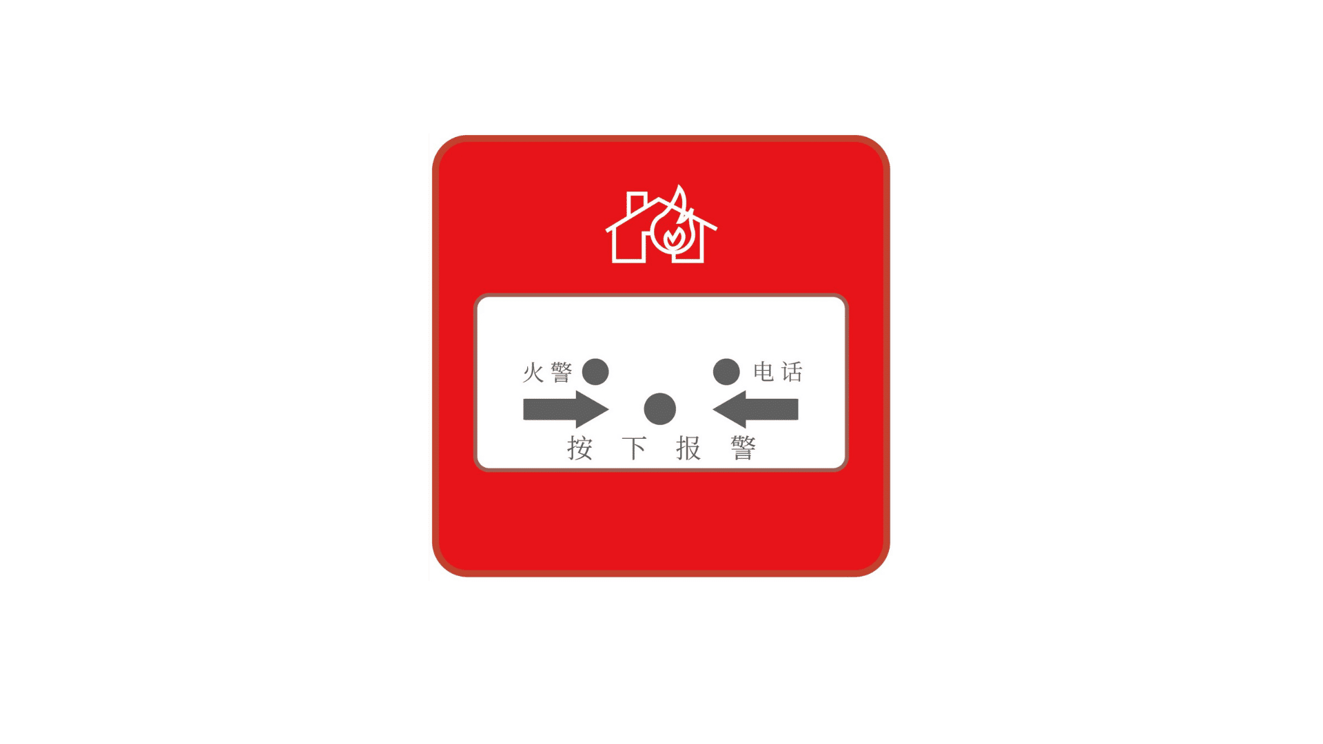
Description
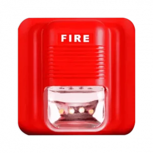
The Fire Emergency Button is a practical and easy-to-use manual fire alarm device designed for fast and reliable emergency response. Featuring one-touch alarm activation, tamper-proof protection, low battery detection, and signal strength monitoring, it ensures safety in a wide range of environments, including factories, warehouses, commercial buildings, hospitals, and more.
Powered by a 32-bit high-performance microprocessor and a long-lasting lithium battery, the device offers stable, reliable performance with minimal power consumption. It is designed for standard national 86-type mounting boxes, making installation simple and convenient.
Key Features
-
Communication Mode: Cat.1 communication.
-
Power Supply: DC 3V using a high-performance CR123A lithium-manganese battery.
-
Alarm Methods:
-
Manual button alarm (manual reset)
-
Tamper-proof alarm
-
-
Heartbeat Function: User-configurable heartbeat interval; provides communication loss indication when offline.
-
Indicators:
-
Signal strength indication
-
Signal transmission indication
-
Device self-check indication
-
-
Warning Functions:
-
Module fault indication
-
SIM card fault warning
-
Failed signal transmission warning
-
Device-to-base station connection failure warning
-
Device-to-service platform communication failure warning
-
Low-voltage warning
-
-
Alarm Output:
-
Panel indicator light
-
Switch output
-
Wireless communication output
-
-
External SIM Card Cover: Simple and convenient SIM card installation.
-
Fire Telephone Interface: Supports fire telephone line jack; detects line breakage, connection, and handset off-hook status.
-
Anti-Tamper Design: Requires tools to remove the device from the mounting surface.
-
Standard Installation: Fits standard 86mm back boxes; can be mounted on various surfaces or bedside 86mm box bases.
On-Site Installation and Testing
-
Remove Mounting Plate: Unscrew the fastening screw at the bottom and slide the device upward.
-
Install Mounting Plate: Secure the plate to the wall or standard 86 box using screws.
-
Insert SIM Card: Lift the metal cover at the SIM slot and insert the SIM card (not required for LoRa communication).
-
Connect Fire Phone Line: Connect the phone line to terminals at the bottom of the device.
-
Power Up: Insert the battery or remove the insulation sheet to activate the device.
-
Self-Test:
-
Red light turns on to indicate power-up
-
Green light stays on during internal self-test
-
-
Signal Strength Display: Four levels:
-
Extremely Poor: Yellow flashes for 1 min
-
Poor: Green flashes 2 times, repeated 3 times
-
Average: Green flashes 3 times, repeated 3 times
-
Good: Green flashes 4 times, repeated 3 times
Install the device where signal is strongest; poor signals increase power consumption.
-
-
Self-Test Errors:
-
1 flash: Module fault
-
2 flashes: SIM card issue
-
3 flashes: Connection failure with base station
-
4 flashes: NB signal or platform communication failure
-
-
Tamper Switch Test: Trigger the switch; one red flash indicates normal operation.
-
Alarm Activation: Press the panel button; the red alarm light turns on. (During self-test, the alarm will not activate.)
-
Alarm Reset: Use the reset key to push the panel upward until it clicks.
-
Fire Phone Indicators:
-
Green off: not connected
-
Solid green: connected, idle
-
Dim/flashing: handset in use
-
Switch Output:
-
Normal: high-impedance state
-
Alarm: connected state
(Ensure alarm output and input device ground wires are connected.)
-
Standby State: Alarm indicator flashes once every 50 seconds.
-
Secure Installation: Use the included screw to fasten the device to the mounting plate; removal requires tools, ensuring tamper-proof security.
This Fire Emergency Button combines reliability, durability, and easy installation, making it an essential component for fire safety in commercial, industrial, and healthcare environments.
| No. | Self-test Result | Cause of Problem | Exception Handling |
|---|---|---|---|
| 1 | After inserting battery, device does not self-test | Device not powered normally, not reset | – |
| 2 | Red light flashes once, lasts 60s | Press the tamper switch several times to discharge empty power, re-insert the battery, check contact with metal contacts. Communication failure, hardware fault | Check if battery power is sufficient. |
| 3 | Red light flashes twice, lasts 60s | Communication failure, IoT card fault | Check card-related issues: Is it inserted well? Activated? Expired? Bound to device? |
| 4 | Red light flashes three times, lasts 60s | Communication failure, no signal | Check if there is signal at the site. |
| 5 | Red light flashes four times, lasts 60s | Communication failure, platform not registered | Check if the device IMEI code is registered on the platform. |

Reviews
There are no reviews yet.